Timer Circuits With 4060B
Build a reliable timer to switch devices on and off - from 30 seconds to 24 hours
electronics | electric circuitThere are many applications for which a timer is very useful to turn a device on or off automatically after a preset interval - for example, switching off an irrigation system after 30 minutes of use, turning off a battery charger to prevent overcharging, etc.
Timing short intervals of milliseconds to minutes can easily be achieved using a NE555 timer chip. Unfortunately, this device is not suitable for timing longer intervals, and so a suitable alternative is required.
Binary Counting with the 4060B

The 4060B (pictured above) is a CMOS binary counter. Using a resistor and a capacitor, the counting speed can be set by the user very easily. The pins of the 4060B integrated circuit output the running count in binary as shown below:
0 = 0000000000
1 = 0000000001
2 = 0000000010
3 = 0000000011
4 = 0000000100
5 = 0000000101
6 = 0000000110
7 = 0000000111
8 = 0000001000
1 = 0000000001
2 = 0000000010
3 = 0000000011
4 = 0000000100
5 = 0000000101
6 = 0000000110
7 = 0000000111
8 = 0000001000
Each of the binary 1's and 0's is called a bit (much as the numbers 0,1,2...8,9 are called digits in the decimal number system). The furthest right bit represents 1, the next to the left represents 2, the next represents 4, the next 8, the next 16 and so on doubling every time you move one position to the left. Therefore 000010000 is binary for 16, and 000100000 is binary for 32.
To keep things simple, let's assume the count is increased by one every second. The rightmost bit (the 1's bit) will be off for one second, on for one second, off for one second and so on...
0000000001, 0000000010, 0000000011
The fifth bit from the right (the 16's bit) is therefore off for 16 seconds (when the count is 0-15), then on for 16 seconds (when the count is 16-31), then off for 16 seconds (when the count is 32-47), and so on.
With this knowledge, we can make a very accurate timer utilising our 4060B binary counter chip. Let's say we want a 16 second timer: we start the 4060B counter from 0, and wait until the 16's bit goes from 0 to 1. At that exact time we know that 16 seconds have elapsed. Similarly if we start the counter again, and wait until the 32's bit goes from 0 to 1, we know that 32 seconds have elapsed.
A timer which can only time, 1, 2, 4, 8, 16, 32, 64, 128, and so on seconds would not be very useful, but since we can adjust the speed of the count, any time interval from seconds to 24+ hours can be accurately timed.
4060B Timer
A schematic of the 4060B chip is provided below:
The pins labelled in red Q4-Q14 are the binary outputs: Q4 for the 16's, Q5 for the 32's, Q6 for the 64's and so on up to Q13 for the 8192's, and Q14 for the 16384's.
Just three external components are required to control the 4060B counter - two resistors and one capactor. The frequency of the internal oscillator (i.e. the speed of the count) is set according to the equation given at the bottom of the schematic below:
Since Q14 represents the 16,384's and Q4 represents the 16's - we know it will take 1,024 times longer (16,384 / 16) for Q14 to flip from 0 to 1 than it takes Q4. So, for an example 2-hour timer (=7,200 seconds), we just need to fine-tune the circuit so that Q4 turns on after 7,200 / 1,024 seconds = 7.03 seconds, knowing that if that is done correctly, after exactly 2 hours Q14 will flip from 0 to 1.
Putting Together the Timer Circuit
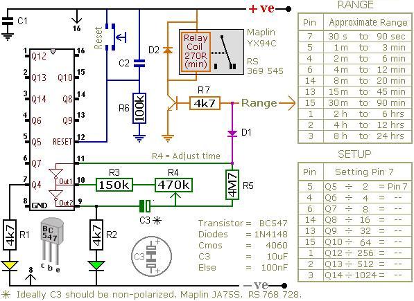
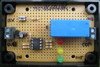
The circuit shown above (from Ron J's Circuit Page) is a timer which energises a relay after a preset time has elapsed. It can be set to time an interval from 30 seconds to 24 hours.
The orange arrow labelled Range should be connected to a pin on the 4060B chip selected from the RANGE table. If for example, you require a timer to time 3 hours, connect it to pin number 1 on the chip since that pin corresponds to the time range 2hrs to 4hrs.
3 hours is 10,800 seconds, and we are using the output from pin 1 to trigger the relay. Looking at the SETUP table entry for pin 1 we see that we divide our target time (10,800 seconds) by 256 to obtain the on/off time for the yellow LED at pin 7 = 42.28 seconds. Therefore, if we adjust the potentiometer R4 so that the yellow LED turns on after approximately 42 seconds, we'll know that the relay will be energised after approximately 3 hours.
The diode D1 makes this a one-shot timer. This means that after the programmed time delay of 3 hours, the relay will stay on until the circuit is reset. If the diode is omitted from the circuit then you get a repeating timer with the relay off for 3 hours, on for 3 hours, off for 3 hours, and so on until the circuit it reset.
NEW For a repeat timer with different ON/OFF durations - for example, 1 hour OFF, 1 minute ON, 1 hour OFF, 1 minute ON etc - click here to read our new article Repeat Timer Circuit.
Buy a Timer Circuit
This is one of the most complicated circuits discussed on the REUK.co.uk website. Therefore, if you need a timer circuit for a particular application, email neil@reuk.co.uk with details of your exact requirements and we'll happily put together a bespoke solution.NEW Have a look at the new REUK Super Timer - our all new repeating relay timer circuit which can be programmed with ON and OFF durations from 1 second to 99 hours.
Additional Information
Every day we receive requests for 12VDC powered repeating timers with various ON and OFF durations designed to control a huge array of different items including irrigation systems, aquarium pumps, battery chargers, testing systems, heating and cooling systems, feeders, and much more. The new REUK Super Timer has been designed to meet these and other requirements while enabling the user to set their own ON and OFF durations for maximum flexibility. The REUK Super Timer is hand made and rigorously tested before despatch.The REUK Super Timer can be programmed with ON and OFF durations of 1-99 seconds, 1-99 minutes, or 1-99 hours. The ON and OFF durations do not have to have the same units or the same values - e.g. it is possible to have a timer which is on for say 3 seconds and then off for 7 hours etc.
Therefore, for most repeat relay timer applications the REUK Super Timer will be suitable - however, if you require a timer which can be programmed with an ON duration of say exactly two and a half minutes, this is not the product for you (since you could set the ON time to be 2 minutes or 3 minutes, but not 2 1/2 minutes).
If the REUK Super Timer is not suitable for your needs, please contact neil@reuk.co.uk with details of your exact requirements and we can put together a special order for you for around the same price.
Powering the Timer
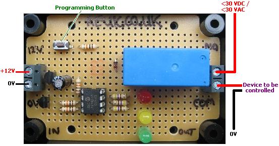
The REUK Super Timer is designed to be powered by 12VDC from either a battery (solar charged or otherwise) or a 12VDC mains transformer. It is possible to power the timer safely with an input voltage of 10-16VDC. Below 10VDC the relay switch will not close and so the timer will not do anything; above 16VDC the relay and other components on the circuit board could be permanently damaged.During OFF cycles the timer draws no more than around 5mA, and during ON cycles it draws around 50mA (= 0.6 Watts @ 12VDC).
Switching Devices with the Relay
The relay fitted to this circuit is rated at 10 Amps (10A @ <250VAC or 10A @ <30VDC), however we only recommend it be used to switch low voltages of <30VDC or <30VAC. If you intend to switch a higher voltage e.g. mains electricity, then we accept your purchase of this item only on the condition that a qualified electrician makes the necessary connections and checks over the circuit and any enclosure you put it into to confirm that everything is correctly earthed and insulated, and that it meets all current safety regulations.Although the rating of the relay is 10 Amps, if you intend to switch an inductive load (anything which generates a magnetic field - e.g. a motor, pump, solenoid, relay etc), the relay should not be used if the device is rated at more than around 4-5 Amps since at start up a surge current in excess of the 10A rating could damage the relay and circuit board.
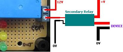
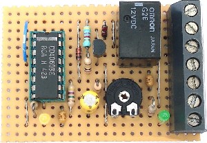
If you have a device to switch which requires a larger relay, either contact neil@reuk.co.uk and request the MOSFET version of this circuit to which you can connect a suitably rated automotive relay, or simply use the on board relay to switch a suitably rated secondary relay (as illustrated above).
Programming the Timer
For the first 10 seconds after the circuit is connected to the power the yellow LED will be lit. During this time it is possible to re-programme the ON and OFF durations of the relay. Press the button once and the yellow LED will turn off. This confirms that you have entered programming mode.For the ON and OFF durations you must enter first the timing units (hours, minutes, or seconds), and the two digit number of those units - e.g. 03 or 47 (from the range 01 to 99).
Programming entails entering six numbers in the following order:
1) ON duration time units: 0 = hours, 1 = minutes, 2 = seconds
2) ON tens: e.g for a 43 second ON time, this value would be 4 (since 4 x 10 = 40). For a 1-9 second duration this value is 0 - e.g. 01, 02, 03,...09
3) ON ones: e.g. for a 43 second ON time, this value would be 3
4) OFF duration time units: -as above-
5) OFF tens: -as above-
6) OFF ones: -as above-
To enter each value in turn, the technique is described below:
The red LED will light up for 2 seconds. If you want to enter a '0' then press the button while the red LED is on. When the red LED turns off, the green LED will start flashing - on for 1.5 seconds, then off for 0.5 seconds. If you want to enter a '1' then press the button while the green LED is lit for the first time. To enter a '2', wait until the green LED turns on for the second time and press the button. To enter a '3' press the button the third time the green LED lights up...and so on.
When you press the button the green LED (or red LED if you are entering a '0') will immediately turn off, and the yellow LED will light up and stay on for one second. This gives you visual confirmation that your input has been accepted and tells you to get ready to enter the next value. When the yellow LED turns off and the red LED lights up again repeat as above to enter the next value.
If you make a mistake while programming, just disconnect the circuit briefly from the power and start again. It is much easier to programme the timer if you prepare yourself beforehand by working out and writing down the six values in order so that you are ready to enter them.
For example, if you want a timer which will be ON for 7 seconds and then OFF for 23 minutes, the ON timer units are seconds ('2'), and the OFF timer units are minutes ('1'). Therefore you would need to enter the following sequence of values:
'2' (seconds - second green LED), '0' (no tens- red LED), '7' (7 ones - seventh green LED), '1' (minutes - first green LED), '2' (2 tens - second green LED), '3' (3 ones - third green LED). So, you would write down
2 red 7 1 2 3
before you programme the timer - note that 'red' is written rather than '0' so you remember to press the button when the red LED is on.If you enter a number greater than 9 for the tens or ones, '9' will be saved. If you enter a number greater than 2 for the time units, '2' will be saved - i.e. your timer will be programmed in seconds.
When you have programmed all six values, the timer will immediately start with the ON cycle closing the relay with the green LED on. When the OFF cycle starts, the green LED will be off. As long as the timer remains connected to the power, it will continue to repeat the ON and OFF cycles with the programmed settings.
The programmed ON and OFF durations are stored in non volatile memory, and so will be retained even when you disconnect the circuit from the power. Therefore, you only need to go through the programming steps if you want to change the ON and/or OFF duration for some reason.
Timer Accuracy
The accuracy of the timer is better than around 1%, i.e. over the course of an hour the timer may gain or lose 30 or so seconds (usually far less). Therefore the timer is not suitable for use where exact timings are required - e.g. if you want something to be turned on at exactly the same time every day (since the times will drift over days and weeks).Related REUK.co.uk Articles
Make a repeat timer circuit with large intervals between ON timesBuild a reliable timer to switch devices on and off - from 30 seconds to 24 hours


0 komentar:
Posting Komentar