
Kamis, 03 Juni 2010
TIMER 556
DISCLAIMER: This timer has not been thoroughly tested and thus, should be considered experimental. Use of this design is entirely at the risk of the user.
Why I did it
It appears the many people have had problems with ejection charge delays ("bonus" delays, need a -5.5 and not -4 or -7, etc.) This made me wonder how hard it would be to make an electronic time delay unit. Since it would be electronic, it wouldn't suffer from the same sort of problems currently found in todays motor's. However, new problems might arise. There was also some lamenting from the 6-C cluster altitude competitors that the existing motor time delays were not long enough to achieve the maximum altitude possible with those models. So I thought I'd make it as skinny as possible to be of use for competitors and easily adjustable for various applications. The commercial timers you can buy today are pretty pricey and some seem rather low-tech, relying on pull-plugs and the like to start the timer. I'd make mine cheap and completely self-contained.
Here's the challenge I undertook. Build an adjustable electronic ejection charge delay timer that will be: BT-5 sized, adjustable over a wide range of times (0.5 to 30 s), inexpensive (<$10), entirely self-contained (no external plugs, wires, etc.) and fire a flashbulb for the ejection charge.
The timer consists of basically four parts: the timer, the timer adjustment, the acceleration sensor and the battery.
Timer
For relatively long time delays (a few to many seconds or even hours if you'd like), the chip of choice is the 555 timer. By adjusting one capacitor and resistor, a wide range of pulse widths are possible. The problem is that a single 555 timer outputs a pulse of a given length immediately following a trigger. I wanted a pulse after a given time delay. So, I needed two 555 timers. The output pulse of the first timer would be the trigger for the second, whose output pulse would fire a flashbulb. These two timers can be found on a single chip, the 556 dual timer, which consists of two independent 555s. Another benefit of the 555 is the relatively high output current of 200 mA. Figure 1 below shows the timer scematic.
There are several technical issues which need to be addressed in using the 555 for long time delays.
The time delay for the 555 is given by 1.1RC, where R and C are the timing resistor and capacitor, respectively. There are maximum practical values for these components. R cannot be much more than a few megaohms due to the minimum charging currents needed by the chip and the maximum C value is typically set by the leakage current internal to the capacitor. Long time delays call for tantalum cpacitors, with low leakage. Although probably not required here, I used them to be safe and also because of their relatively small size.
I also wanted the second timer to be triggered by the trailing edge of the first timer's output pulse and not anytime else. This required a differentiator circuit between the output of the first and the second timers.
The characteristics of the launch sensor will dictate wheteher you want a differentiator or integrator between it and the first timer. If you desire some immunity to premature triggers, an integrator can delay the trigger for a fraction of a second. This will add to your total time delay and requires a good g-switch that will stay closed under acceleration. If you are unsure of your g-switch or if it will stay closed well after launch, a differentiator should be used. In this case a safe/arm switch should be added to prevent setting off the ejection charge when jostling the rocket.
Timer adjustment
In order to get a variety of repeatable time delays, I had to gang together either a group of resistors of capacitors. I chose to go with resistors since they can be found in a wider array of values than the capacitors and they can be found with tighter tolerances as well. I made a variable resistor by soldering the resistors across the terminals of a 6-pin DIP switch, with the switches connected in series. This way, when the switch is off, the corresponding resistor gets its value added to the timing resistor total. When the switch is on, the resistor is shorted out and the resistor does not add to the total. See figure 2 below. With the values shown, this timer will allow delays from 0.5 to 31.5 s in 0.5 s increments.
Launch sensor
I wanted my timer to sense liftoff and set the delays from that point. A g-switch would have been ideal. I found several manufacturers who sell them, but since they are mil-spec parts, they tend to be quite expensive ($10-$20 apiece in small quantities).
I made a few home-made g-switches to save some money. The first was made by epoxying a small ball of lead on top of a modified pushbutton switch. This switch was opened, the spring discarded and replaced by a small sliver of foam. This would close at liftoff. However, I worried about the reliability of such a switch. I also opened a tiny 5V relay and soldered a weight to the movable arm of the relay. This looked to be much more reliable than the first switch but was still a little expensive ($3). I recently found a very low force (<10 gram) tiny switch from an electronics surplus catalog for $0.30, I hope they work well.
A mercury switch could be used as well, but is not exactly what I wanted, as it would sense the rocket decelleration after motor burnout and not the launch. I was hesitant about this since the decelleration is much lower than the launch acceleration. Using the mercury switch may also cause some timing problems with long-burn motors that are severely regressive, since the rocket may acually be decellerating when the motor is still burning. However, the point at which the rocket starts to decellerate can still be found using simulation, and the appropriate time delay chosen. Delay times for most motors with relatively constant thrust would be chosen just like the pyrotechnic delays currently used.
A pull plug or lever switch against the launch rod could also be used, but would violate my self-containment goal. However, this option is quite inexpensive.
Battery
I needed a battery with from 5-15 V that would fit in a BT-5. A little perusal of the battery display at a local store came up with the A23 battery. This is 12 V and has the diameter of a AAA battery and about 2/3 the length. A plastic N-cell battery holder will fit in a BT-5 if the corners are trimmed off. This battery will just barely fire an AG-1 flashbulb by itself, so I added a 1000 uF capacitor discharged through a HEXFET to provide the high peak current to fire the flashbulb.
Timer Schematics
![[Schematic]](https://lh3.googleusercontent.com/blogger_img_proxy/AEn0k_s0jnhzp5hVbeUSDg8Xq6T8OmIEDgRNM4prjiNPlKKlCG67kBBKaENuTiH-h4OpcfkDesx9xfyS7XN2pMCemc6jI3cY5Yq79KnQ-yvpuSh2XaTOiWrPU8QfKwBJK2u7Cw=s0-d)
Test Results
I have flown the prototype with the relay g-switch several times with good results. I have made up PC boards and have the components (except for the g-switch and battery) to make the timers available in kit form for $15. The PC board version is *MUCH* neater than my prototype.
![[Schematic]](https://lh3.googleusercontent.com/blogger_img_proxy/AEn0k_tja_npEGA774FPrAZaMv914TB_nqR-Sd3PgWugwuGgyP0lEotdxfK0fEQWaVlc5akrNA0J71B7txxthKPHHseTkdiaLtwbCkuULT9AeK4C-AhpkHkwNFjWqLbDktoqlQ=s0-d)
0.01 uF capacitors have a red stripe on the package, the 1 uF caps a blue stripe and 4.7 uF a green stripe.
You should probably solder the right most 1uF capacitor after the 556, or at least with the 556 in place since I didn't leave much room for that part.
The drain side of the IRFD110 has the two pins connected.
Bend up the headers to make room for the connectors, or you can solder two conductor wire directly to the board for remote on/off and flashbulb connections.
battery with snap holder will work well if minimum size is not an issue.
Small detector switch with lead ball on plunger (not tested)
Small relay with weight on lever arm ( used in prototype but needs
major surgery to fit in BT-5 on PC board)
Larger:
Electronics Goldmine mechanical airbag g-switch (not in catalog any more)
Lever switch against launch rod (requires use of differentiator circuit(see below))
Integrator (included in kit but not tested)
This requires the g-switch to activate for about 0.5 s before timer is initiated. This will guard against false triggers but requires a reliable g-switch. May inhibit second stage from triggering if g-switch is on at end of timing interval. Probably not good for short timing intervals since decay time after g-switch opens is about 5 s.
#2 - 1.0 s
#3 - 2.0 s
#4 - 4.0 s
#5 - 8.0 s
#6 - 16.0 s
So that an 11 second interval would have 2, 3 and 5 off, the rest on.
The 22uF capacitor is a 20% tolerance part so check the long interval to see how close you are to 16 s, the lower
switches should be nearly exact factors of 2 smaller ( the resistors are 1% tolerance).
Why I did it
It appears the many people have had problems with ejection charge delays ("bonus" delays, need a -5.5 and not -4 or -7, etc.) This made me wonder how hard it would be to make an electronic time delay unit. Since it would be electronic, it wouldn't suffer from the same sort of problems currently found in todays motor's. However, new problems might arise. There was also some lamenting from the 6-C cluster altitude competitors that the existing motor time delays were not long enough to achieve the maximum altitude possible with those models. So I thought I'd make it as skinny as possible to be of use for competitors and easily adjustable for various applications. The commercial timers you can buy today are pretty pricey and some seem rather low-tech, relying on pull-plugs and the like to start the timer. I'd make mine cheap and completely self-contained.
Here's the challenge I undertook. Build an adjustable electronic ejection charge delay timer that will be: BT-5 sized, adjustable over a wide range of times (0.5 to 30 s), inexpensive (<$10), entirely self-contained (no external plugs, wires, etc.) and fire a flashbulb for the ejection charge.
The timer consists of basically four parts: the timer, the timer adjustment, the acceleration sensor and the battery.
Timer
For relatively long time delays (a few to many seconds or even hours if you'd like), the chip of choice is the 555 timer. By adjusting one capacitor and resistor, a wide range of pulse widths are possible. The problem is that a single 555 timer outputs a pulse of a given length immediately following a trigger. I wanted a pulse after a given time delay. So, I needed two 555 timers. The output pulse of the first timer would be the trigger for the second, whose output pulse would fire a flashbulb. These two timers can be found on a single chip, the 556 dual timer, which consists of two independent 555s. Another benefit of the 555 is the relatively high output current of 200 mA. Figure 1 below shows the timer scematic.
There are several technical issues which need to be addressed in using the 555 for long time delays.
The time delay for the 555 is given by 1.1RC, where R and C are the timing resistor and capacitor, respectively. There are maximum practical values for these components. R cannot be much more than a few megaohms due to the minimum charging currents needed by the chip and the maximum C value is typically set by the leakage current internal to the capacitor. Long time delays call for tantalum cpacitors, with low leakage. Although probably not required here, I used them to be safe and also because of their relatively small size.
I also wanted the second timer to be triggered by the trailing edge of the first timer's output pulse and not anytime else. This required a differentiator circuit between the output of the first and the second timers.
The characteristics of the launch sensor will dictate wheteher you want a differentiator or integrator between it and the first timer. If you desire some immunity to premature triggers, an integrator can delay the trigger for a fraction of a second. This will add to your total time delay and requires a good g-switch that will stay closed under acceleration. If you are unsure of your g-switch or if it will stay closed well after launch, a differentiator should be used. In this case a safe/arm switch should be added to prevent setting off the ejection charge when jostling the rocket.
Timer adjustment
In order to get a variety of repeatable time delays, I had to gang together either a group of resistors of capacitors. I chose to go with resistors since they can be found in a wider array of values than the capacitors and they can be found with tighter tolerances as well. I made a variable resistor by soldering the resistors across the terminals of a 6-pin DIP switch, with the switches connected in series. This way, when the switch is off, the corresponding resistor gets its value added to the timing resistor total. When the switch is on, the resistor is shorted out and the resistor does not add to the total. See figure 2 below. With the values shown, this timer will allow delays from 0.5 to 31.5 s in 0.5 s increments.
Launch sensor
I wanted my timer to sense liftoff and set the delays from that point. A g-switch would have been ideal. I found several manufacturers who sell them, but since they are mil-spec parts, they tend to be quite expensive ($10-$20 apiece in small quantities).
I made a few home-made g-switches to save some money. The first was made by epoxying a small ball of lead on top of a modified pushbutton switch. This switch was opened, the spring discarded and replaced by a small sliver of foam. This would close at liftoff. However, I worried about the reliability of such a switch. I also opened a tiny 5V relay and soldered a weight to the movable arm of the relay. This looked to be much more reliable than the first switch but was still a little expensive ($3). I recently found a very low force (<10 gram) tiny switch from an electronics surplus catalog for $0.30, I hope they work well.
A mercury switch could be used as well, but is not exactly what I wanted, as it would sense the rocket decelleration after motor burnout and not the launch. I was hesitant about this since the decelleration is much lower than the launch acceleration. Using the mercury switch may also cause some timing problems with long-burn motors that are severely regressive, since the rocket may acually be decellerating when the motor is still burning. However, the point at which the rocket starts to decellerate can still be found using simulation, and the appropriate time delay chosen. Delay times for most motors with relatively constant thrust would be chosen just like the pyrotechnic delays currently used.
A pull plug or lever switch against the launch rod could also be used, but would violate my self-containment goal. However, this option is quite inexpensive.
Battery
I needed a battery with from 5-15 V that would fit in a BT-5. A little perusal of the battery display at a local store came up with the A23 battery. This is 12 V and has the diameter of a AAA battery and about 2/3 the length. A plastic N-cell battery holder will fit in a BT-5 if the corners are trimmed off. This battery will just barely fire an AG-1 flashbulb by itself, so I added a 1000 uF capacitor discharged through a HEXFET to provide the high peak current to fire the flashbulb.
I have flown the prototype with the relay g-switch several times with good results. I have made up PC boards and have the components (except for the g-switch and battery) to make the timers available in kit form for $15. The PC board version is *MUCH* neater than my prototype.
You should probably solder the right most 1uF capacitor after the 556, or at least with the 556 in place since I didn't leave much room for that part.
The drain side of the IRFD110 has the two pins connected.
Bend up the headers to make room for the connectors, or you can solder two conductor wire directly to the board for remote on/off and flashbulb connections.
Hints
Battery:
For a true BT-5 timer, a radio shack N-cell holder can be trimmed down to fit. This will accommodate an A23 12 V pager battery. There are also skinny NiCd battery stacks that might fit and could be soldered directly to the timer if a charging connection is added. I have a 7.2 V NiCd that fits in a BT-5 but I haven't tested it yet. A 9 Vbattery with snap holder will work well if minimum size is not an issue.
G-switch options:
BT-5 compatible: Mercury switch to detect decelleration at motor burnout.Small detector switch with lead ball on plunger (not tested)
Small relay with weight on lever arm ( used in prototype but needs
major surgery to fit in BT-5 on PC board)
Larger:
Electronics Goldmine mechanical airbag g-switch (not in catalog any more)
Lever switch against launch rod (requires use of differentiator circuit(see below))
Integrator vs differentator g-switch circuits:
Differentiator: Good for use with unreliable g-switch since any intermittent switch closing will trigger timer. Will make timer prone to false triggers if g-switch is sensitive. This may make ejection charge go off on the pad if rocket is jostled. Required for switch that stays on since a constant on (trigger to ground) will inhibit the second stage of the timer from triggering.Integrator (included in kit but not tested)
This requires the g-switch to activate for about 0.5 s before timer is initiated. This will guard against false triggers but requires a reliable g-switch. May inhibit second stage from triggering if g-switch is on at end of timing interval. Probably not good for short timing intervals since decay time after g-switch opens is about 5 s.
Time interval setting
Turn *off* DIP switches to set time intervals: #1 - 0.5 s#2 - 1.0 s
#3 - 2.0 s
#4 - 4.0 s
#5 - 8.0 s
#6 - 16.0 s
So that an 11 second interval would have 2, 3 and 5 off, the rest on.
The 22uF capacitor is a 20% tolerance part so check the long interval to see how close you are to 16 s, the lower
switches should be nearly exact factors of 2 smaller ( the resistors are 1% tolerance).
Darkroom Timer v2.0A for PCB Exposure Box
PIC based automatic timer for a PCB exposure box
author: Vassilis Papanikolaou
PIC based automatic timer for a PCB exposure box
author: Vassilis Papanikolaou
This is an improved version of the Darkroom Timer originally created by Stan Ockers (1999). Some extra features were added and the PIC code was modified accordingly
Lamp(s) light at start of timing and turn off when timer reaches zero.
The complete schematic, PCB and silkscreen are available in high resolution pdf format. The component values are clearly indicated on the silkscreen. The modified source code is available in asm and hex format (compiled in MPLAB).

Darkroom Timer Schematic

Darkroom Timer PCB

Darkroom Timer Silkscreen
Parts list
System boardR1 - R7 150 Ω 1/4W 5%
R8 - R11 4.7 KΩ 1/4W 5%
R12 - R13 1 KΩ 1/4W 5%
R14 100 Ω 1/4W 5%
R15 75 Ω 1/4W 5%
R16 10 KΩ 1/4W 5%
C1 - C2 22 pF
C3 2200 μF/25V electrolytic
C4 - C6 100 nFD5 1N4001/4004/4007
F1 1A Fuse (with socket and cap)
B1 1A Bridge rectifier
IC1 PIC16F84AP Microcontroller (4MHz clock) (with IC socket)
IC2 74HC4543 BCD to 7-segment decoder (with IC socket)
IC3 7812 voltage regulator
IC4 7805 voltage regulator
PL1 14 pin connector
JP2 6 pin header
K1 12V DC / 220V AC Relay
OK1 CNY17-1 OptocouplerOSC1 4MHz Crystal
Q1 - Q4 BC557/558 PNP Transistror
Q5 BC547/548 NPN Transistor
Q6 BC557/558 PNP Transistror
Q7 2N2222 NPN Transistor
TR1 220VAC/15VAC 1VA PCB TransformerX1 - X3 2 pin WAGO screw clampLed boardD1 - D4 Common cathode 7-segment display
LED1 - LED2 Orange Led 3 mm
JP1 Not a connector, cable is soldered directly on the back of the led PCBBox frontBicolor common cathode led (green-red)
3 push-button switches
Switch connectionsConnector X1 is connected to the lamp(s)
Connector X2 is connected to 220VAC mains
Connector X3 is connected to the mains switchLed board is connected to system board via connector PL1
PhotosThe system board
The led board
Connection between system and led boards (PL1)
Connection of switches and bicolor led (JP2) done in breadboard
Normally switches and bicolor led are attached to the front of exposure box


Board testing with externally applied DC on the 7812 regulator (for safety reasons)
A real time video is also available. Pay attention to the blinking leds between minutes and seconds and the bicolor led indicating both operation (red) and standby (green). Unfortunately there is no sound for the relay clicks to be heard !


The second video shows some real action ! A common light bulb turns on and off exactly like in a PCB exposure box.
 Download whole project in .doc format (without pdf files) - 3,57MB Download additional photos in .doc format - 3,88MB Download whole project in .zip format (with pdf files) - 3,97MB
 Photos of the Darkroom timer installed on the exposure unit


The system board, LCD board and switches installed
Notice the common ground for push buttons and bicolor led (JP2 Pin 6)

The darkroom timer during operation
A third video shows the pcb exposure box in operation. A plain lamp was used in this video but when you have UV lamps installed, never leave the top lid open !IC 555 One-Shot Timer Project
555 One-Shot Timer Project

I suppose that if you set out to build a Blaster Pistol, you should expect that somewhere along the way you might be required to construct a Uranium PU-36 Space Modulator, but I wasn’t prepared to build a Oneshot Monostable Multivibrator.
When I first thought about adding light and sound to my raygun project, I really just envisioned using the gun’s trigger as a switch to turn on the sound and light effects – done. But I quickly realized that the effects would need to pulse in a consistent and controlled manner. With each trigger pull, you should get a pulse of light, and a blast sound. To seem convincing, the duration of the pulse should be the same each time and only happen once when you pull the trigger even if you were to keep the trigger switch closed. And you don’t want the sound effect looping over and over or getting cut short.
The 555 Timer IC
When I surveyed my expert sources for advice about how to better control my effects, the resounding answer was “use a 555 timer”.I have built a lot of electronic kits in my day, but for some reason every time I try to tinker with building my own circuits from scratch, I fail miserably. I have tried a number of times to teach myself the fundamentals of electronics by getting some components and building a small amplifier or some such project, but it never seems to work out. This time I was determined to make it work, so I researched 555 timer circuits, bought a few of the IC’s and gave it another try. But before getting into it, I went to Ebay and bought a huge lot of resistors, capacitors, a breadboard, jumpers, and other components that someone else had cast off, probably after becoming frustrated with learning electronics. I remembered from my previous forays that one of the most frustrating things about experimenting was not having the right resistor or capacitor on hand and having to run to radio shack and pay $10.00 for .30 cents worth of parts and still not get what you need.

Even with great determination and much time devoted to the project, it was still sort of frustrating. You see, the 555 has been in use since the early 1970’s and seems to have been the mainstay IC of homebrew electronics experimenters until PICs became ubiquitous. There are literally thousands of circuits out there that are built around the 555, and I found 5 or 6 that looked to be just what I needed. However, the first three designs that I tried all failed to work as advertised (if they did anything at all). I was remember why I had given up on circuit craft those other times.
Finally, over on Rob Paisley’s site I found a circuit that looked a little different than the standard 555 one-shot.
This one actually worked.


Once I had the timer pulsing an LED on the breadboard, I started adding the actual effects that I wanted to use in my project. I want the firing sequence to do 3 things:
1) Pulse a cluster of super bright red LEDs with a forward blast of light.
2) Shoot out a blast of red laser light that with project a nice red spot all the way across a well-lit room.
3) Make a nice laser gun sound that is synchronized with the lights.
I bought a little laser diode assembly on ebay that came with a focusable collimating lens, which allows you to spread the usual pinpoint laser dot out into a bigger red blob.
For the sound effect, I bought a Radio Shack recordable sound module. To get the sound onto the module, I cut of the microphone and clipped the leads to an RCA-to-mini stereo cable and plugged that into the headphone jack of my computer. By pushing the record button on the module and the play button on the computer at the same time I was able to load up a laser sound that I found somewhere on the web.
Adding Transistors
When I added the laser to the circuit, things stared going haywire. I guessed that the laser, LED, and sound board circuits would need to be isolated from each other, so I used the signal from the 555 to trigger an NPN transistor to switch on the LEDs. Then I ran a jumper from the emitter of the LED transistor to trigger the another transistor to turn on the laser.Things were better but still erratic, so I added diodes to the transistor base connections, which fixed the problems. I removed the play button from the sound module and soldered on some wires in its place. I used a third transistor to trigger the sound board. I also had to add diodes to the sound board power leads, or it would cause the laser to put out only a faint glow. It’s all very mysterious.
Building The Circuit

Once I had all the bugs worked out, I dismantled the breadboard version and rebuilt the circuit on a piece of perforated circuit board. Even though I used the exact same components that I had used in the breadboard setup, it didn’t work quite right when I built it on the circuit board. I had to change the timing resistor to get the correct timer pulse, and use a different current limiting resistor to make the laser come on. Lots of trial and error, but I have a great sense of accomplishment for getting further than I have in my previous attempts at homebrew electronics.

Timer with buzzer and optocoupler by IC 4060
This small Timer circuit by sam(good electronic man).
sam say “A small circuit that can find a lot applications of measurement time. She has the possibility us inform with sound signal from the BZ1. At the same time, exist the possibility drive a external circuit via the optocoupler IC2, after we connect the applicable circuit in contacts [ A ] and [ B ]. The circuit is based on IC1 (4060), which include in his inside, oscillator and a binary divider of 14 stage. The frequency operation of oscillator is determined by a circuit R-C that connected in pins 9,10,11 of IC1. We give supply in the circuit, with switch S1,…”

Read more : http://users.otenet.gr/~athsam/timer_with_buzzer_and_optocupler.htm
sam say “A small circuit that can find a lot applications of measurement time. She has the possibility us inform with sound signal from the BZ1. At the same time, exist the possibility drive a external circuit via the optocoupler IC2, after we connect the applicable circuit in contacts [ A ] and [ B ]. The circuit is based on IC1 (4060), which include in his inside, oscillator and a binary divider of 14 stage. The frequency operation of oscillator is determined by a circuit R-C that connected in pins 9,10,11 of IC1. We give supply in the circuit, with switch S1,…”

Read more : http://users.otenet.gr/~athsam/timer_with_buzzer_and_optocupler.htm
IC 555 SEBAGAI TIMER ASTABIL
555 Timer as an Astable Multivibrator
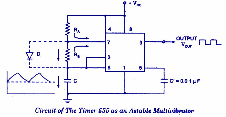
An astable multivibrator, often called a free-running multivibrator, is a rectangular-wave generating circuit. Unlike the monostable multivibrator, this circuit does not require any external trigger to change the state of the output, hence the name free-running. Before going to make the circuit, make sure your 555 IC is working. For that go through the article: How to test a 555 IC for working An astable multivibrator can be produced by adding resistors and a capacitor to the basic timer IC, as illustrated in figure. The timing during which the output is either high or low is determined by the externally connected two resistors and a capacitor. The details of the astable multivibrator circuit are given below.
- 555-Astable-Multivibrator
Take a look @ 555 Ic Pin configuration and 555 block diagram before reading further.
Pin 1 is grounded; pins 4 and 8 are shorted and then tied to supply +Vcc, output (VOUT is taken form pin 3; pin 2 and 6 are shorted and the connected to ground through capacitor C, pin 7 is connected to supply + VCC through a resistor RA; and between pin 6 and 7 a resistor RB is connected. At pin 5 either a bypass capacitor of 0.01 F is connected or modulation input is applied.
Astable Multivibrator Operation
For explaining the operation of the timer 555 as an astable multivibrator, necessary internal circuitry with external connections are shown in figure.
- Astable-Multivibrator-Operation
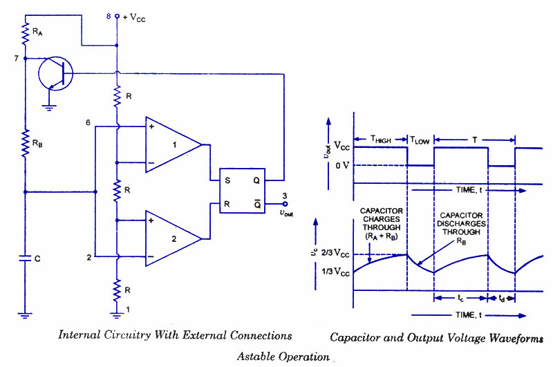
In figure, when Q is low or output VOUT is high, the discharging transistor is cut-off and the capacitor C begins charging toward VCC through resistances RA and RB. Because of this, the charging time constant is (RA + RB) C. Eventually, the threshold voltage exceeds +2/3 VCC, the comparator 1 has a high output and triggers the flip-flop so that its Q is high and the timer output is low. With Q high, the discharge transistor saturates and pin 7 grounds so that the capacitor C discharges through resistance RB with a discharging time constant RB C. With the discharging of capacitor, trigger voltage at inverting input of comparator 2 decreases. When it drops below 1/3VCC, the output of comparator 2 goes high and this reset the flip-flop so that Q is low and the timer output is high. This proves the auto-transition in output from low to high and then to low as, illustrated in fig ures. Thus the cycle repeats.
Astable Multivibrator using 555 IC -Design method
The time during which the capacitor C charges from 1/3 VCC to 2/3 VCC is equal to the time the output is high and is given as tc or THIGH = 0.693 (RA + RB) C, which is proved below.
Voltage across the capacitor at any instant during charging period is given as,vc=VCC(1-et/RC)
The time taken by the capacitor to charge from 0 to +1/3 VCC
1/3 VCC = VCC (1-et/RC)
The time taken by the capacitor to charge from 0 to +2/3 VCC
or t2 = RC loge 3 = 1.0986 RC
So the time taken by the capacitor to charge from +1/3 VCC to +2/3 VCC
tc = (t2 – t1) = (10986 – 0.405) RC = 0.693 RC
Substituting R = (RA + RB) in above equation we have
THIGH = tc = 0.693 (RA + RB) C
where RA and RB are in ohms and C is in farads.
The time during which the capacitor discharges from +2/3 VCC to +1/3 VCC is equal to
the time the output is low and is given as
td or TL0W = 0.693 RB C where RB is in ohms and C is in farads The above equation is worked out as follows: Voltage across the capacitor at any instant during discharging period is given as
vc = 2/3 VCC e- td/ RBC
Substituting vc = 1/3 VCC and t = td in above equation we have
+1/3 VCC = +2/3 VCC e- td/ RBC
Or td = 0.693 RBC
Overall period of oscillations, T = THIGH + TLOW = 0.693 (RA+ 2RB) C , The frequency of oscillations being the reciprocal of the overall period of oscillations T is given as
f = 1/T = 1.44/ (RA+ 2RB)C
Equation indicates that the frequency of oscillation / is independent of the collector supply voltage +VCC.
Often the term duty cycle is used in conjunction with the astable multivibrator.
The duty cycle, the ratio of the time tc during which the output is high to the total time period T is given as
% duty cycle, D = tc / T * 100 = (RA + RB) / (RA + 2RB) * 100
From the above equation it is obvious that square wave (50 % duty cycle) output can not be obtained unless RA is made zero. However, there is a danger in shorting resistance RA to zero. With RA = 0 ohm, terminal 7 is directly connected to + VCC. During the discharging of capacitor through RB and transistor, an extra current will be supplied to the transistor from VCC through a short between pin 7 and +VCC. It may damage the transistor and hence the timer.
However, a symmetrical square wave can be obtained if a diode is connected across resistor RB, as illustrated in dotted lines in figure. The capacitor C charges through RA and diode D to approximately + 2/3VCC and discharges through resistor RB and terminal 7 (transistor) until the capacitor voltage drops to 1/3 VCC. Then the cycle is repeated. To obtain a square wave output, RA must be a combination of a fixed resistor R and a pot, so that the pot can be adjusted to give the exact square wave.
Although the timer 555 has been used in a wide variety of often unique applications it is very hard on its power supply lines, requiring quite a bit of current, and injecting many noise transients. This noise will often be coupled into adjacent ICs falsely triggering them. The 7555 is a CMOS version of the 555. Its quiescent current requirements are considerably lower than that of 555, and the 7555 does not contaminate the power supply lines. It is pin compatible with the 555. So this CMOS version of the 555 should be the first choice when a 555 timer IC is to be used.
Read more: http://www.circuitstoday.com/555-timer-as-an-astable-multivibrator#ixzz0pmSn5C7H
Under Creative Commons License: Attribution
Timer IC 555 SEBAGAI Monostable Multivibrator
555 Timer as Monostable Multivibrator
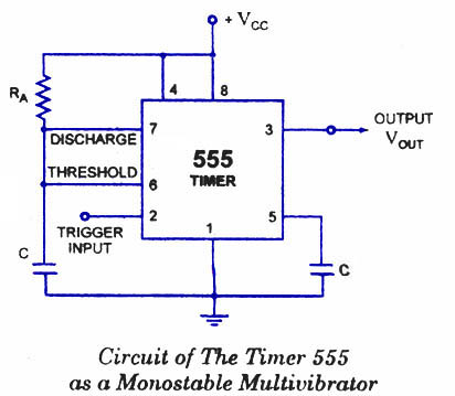
A monostable multivibrator (MMV) often called a one-shot multivibrator, is a pulse generator circuit in which the duration of the pulse is determined by the R-C network,connected externally to the 555 timer. In such a vibrator, one state of output is stable while the other is quasi-stable (unstable). For auto-triggering of output from quasi-stable state to stable state energy is stored by an externally connected capacitor C to a reference level. The time taken in storage determines the pulse width. The transition of output from stable state to quasi-stable state is accomplished by external triggering. The schematic of a 555 timer in monostable mode of operation is shown in figure.
555-timer-monostable-multivibrator
Monostable Multivibrator Circuit details
Pin 1 is grounded. Trigger input is applied to pin 2. In quiescent condition of output this input is kept at + VCC. To obtain transition of output from stable state to quasi-stable state, a negative-going pulse of narrow width (a width smaller than expected pulse width of output waveform) and amplitude of greater than + 2/3 VCC is applied to pin 2. Output is taken from pin 3. Pin 4 is usually connected to + VCC to avoid accidental reset. Pin 5 is grounded through a 0.01 u F capacitor to avoid noise problem. Pin 6 (threshold) is shorted to pin 7. A resistor RA is connected between pins 6 and 8. At pins 7 a discharge capacitor is connected while pin 8 is connected to supply VCC.
555 IC Monostable Multivibrator Operation.

555 monostable-multivibrator-operation
For explaining the operation of timer 555 as a monostable multivibrator, necessary internal circuitry with external connections are shown in figure.
The operation of the circuit is explained below:
Initially, when the output at pin 3 is low i.e. the circuit is in a stable state, the transistor is on and capacitor- C is shorted to ground. When a negative pulse is applied to pin 2, the trigger input falls below +1/3 VCC, the output of comparator goes high which resets the flip-flop and consequently the transistor turns off and the output at pin 3 goes high. This is the transition of the output from stable to quasi-stable state, as shown in figure. As the discharge transistor is cutoff, the capacitor C begins charging toward +VCC through resistance RA with a time constant equal to RAC. When the increasing capacitor voltage becomes slightly greater than +2/3 VCC, the output of comparator 1 goes high, which sets the flip-flop. The transistor goes to saturation, thereby discharging the capacitor C and the output of the timer goes low, as illustrated in figure.
Thus the output returns back to stable state from quasi-stable state.
The output of the Monostable Multivibrator remains low until a trigger pulse is again applied. Then the cycle repeats. Trigger input, output voltage and capacitor voltage waveforms are shown in figure.
Monostable Multivibrator Design Using 555 timer IC
The capacitor C has to charge through resistance RA. The larger the time constant RAC, the longer it takes for the capacitor voltage to reach +2/3VCC.
In other words, the RC time constant controls the width of the output pulse. The time during which the timer output remains high is given as
tp = 1.0986 RAC
where RA is in ohms and C is in farads. The above relation is derived as below. Voltage across the capacitor at any instant during charging period is given as
where RA is in ohms and C is in farads. The above relation is derived as below. Voltage across the capacitor at any instant during charging period is given as
vc = VCC (1- e-t/RAC)
Substituting vc = 2/3 VCC in above equation we get the time taken by the capacitor to charge from 0 to +2/3VCC.
So +2/3VCC. = VCC. (1 – e-t/RAC) or t – RAC loge 3 = 1.0986 RAC
So pulse width, tP = 1.0986 RAC s 1.1 RAC
The pulse width of the circuit may range from micro-seconds to many seconds. This circuit is widely used in industry for many different timing applications.
Langganan:
Postingan (Atom)


